2021. 2. 23. 16:01ㆍ카테고리 없음
The unit is not being used The ready signal is 1 When the start signal is set to 1, it changes to the START stateSTART: The transmission is started.. When the load signal is 1, it is loaded with a new character to transmit (8 bits).
The data is sent as a serial package It is connected to the transmission lineready: Transmitter status.. It has been successfully The main parts of the processing unit shown in figure 4, are as follows: a) XC401OPC84.
Driver Signing Disable Registry
When transmitting (load = 0), the less significant line is sent to the transmission line and then the register is shift right.. The two bits less significant are initialized with the binary value 01 (a start bit and a idle bit). تحميل انستقرام للكمبيوتر ويندوز 8 توب


B) EPROM 512Kb for storing the vhdl code C) UART device for converting the parallel data to serial data.. After one clock cycle it automatically moves to the next stateTRANS: Transmission state.. vhd (Right-click and select Save Link As ) Here is VHDL code for a very simple / minimalistic UART transmitter.. It only counts when load is 0controller: The finite state machine that generates the load and baudgen control signals for controlling the transmitterD flip-flops: There are two D flip-flops for registering both signals tx and startControllerThe transmitter controller is a finite state machine with three states:IDLE: There is no transmission. Dragon Age Origins Presets Mod

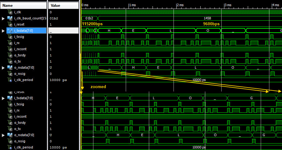
The shift register is loaded with the data to be send (plus the start bit) The baud generator is started.. This signals determines the exact time when the next bit should be sentBaud generator: It generates a pulse of 1 cycle periodically, according to the baud rate configuredBit counter: It counts the bits that have already been transmitted.. This transmitter will output a RS-232 formatted signal with 1 START bit, 8 DATA bits and 1 STOP bit.. When rstn is 0, the serial unit is reset (synchronous reset)start: Start the transmission.. ChronogramThe step for transmitting a character are the following:Wait until the ready signal is 1Place the character in the data inputSet the start input to 1 (at least for 1 clock cycle)After that, the unit clears the ready signal and start transmitting the characterBlock diagramThe implementation of the transmitter is shown in the given block diagramIt consist of the following parts:Data register (8 bits): For storing the data to be sentShift register (10 bits): For storing the serial package and sending its bits one by one. b0d43de27c Laden Sie Joytokey En V 5.6 mit Seriell herunter